Mechanical fuel injection systems had been developed during war time for aircraft engines. Lucas developed a system for use in cars and this early article originally published in November 1956 shows the then current development for use in racing cars..
Monday, December 28, 2015
Tuesday, October 13, 2015
TR7 removable hardtops
I bought a detachable hardtop for my TR7 convertible to make it just a little more practical.


It has done a good job of keeping the rain and snow off me. It turns out that my hardtop is made by Honeybourne Mouldings rather than Lenham. Honeybourne hardtops are available new again after the firm reintroduced them. Apparently the design had to be renewed as the original moulds were no longer up to the job.
The windows are different on a Lenham as shown below.
The rear window in a Lenham is the same size amd shape as in the TR7 fixed head. Before I realised I had a Honeybourne rather than a Lenham I bought a heated rear windows from a TR7 fixed head as I fancied having a demistable back window.
Both Lenham and Honeybourne hardtops fix to the car in the same way,
 clipping to the header rail at the front and by J bolts to the hood frame near the B post of the car.

 A German design.
A DIY Amerian made hardtop.
Smooth Line hardtop from USA. Still being made as I write this.
http://www.smoothline.com/triumph.php
Triumph TR 7-8 Hardtop with Haartz Vinyl Exterior view above. Triumph TR 7-8 Hardtop Interior view below.
The SnugTop design as made in the USA.
 The 3rd May 1980 edition of Motor magazine contained details of two new accessories for the TR7. A roll over protection bar and a detachable hardtop.


It has done a good job of keeping the rain and snow off me. It turns out that my hardtop is made by Honeybourne Mouldings rather than Lenham. Honeybourne hardtops are available new again after the firm reintroduced them. Apparently the design had to be renewed as the original moulds were no longer up to the job.
 |
| Honeybourne TR7 hardtop |
 |
| Lenham hardtop |
Both Lenham and Honeybourne hardtops fix to the car in the same way,


Alternative hardtops

Lenham
 |
| Lenham hardtop advert |
DIY Amerian
 |
| DIY Amerian hardtop 1 |
 |
| DIY Amerian hardtop 2 |
Smooth Line
 |
| Smooth Line hardtop |
http://www.smoothline.com/triumph.php
 |
| Smooth Line hardtop exterior |
 |
| Smooth Line hardtop interior |
SnugTop
 |
| SnugTop hardtop 1 |
 |
| SnugTop hardtop 2 |
Extract from Motor

Cover for TR7
QUICK OFF the mark, Lenham have introduced a detachable hard-top for the Triumph TR7 convertible. Made from glass fibre the roof is supplied in black or may be painted to match the car. The tinted rear window has heating elements, the interior is fully lined with cloth and the side windows open The roof can be supplied with a tilt or take-out Amilite sun-roof (as can all Lenham hardtops). Prices with VAT are: £345 and £488.75 with Amilite sunroof. Lenham Motor Co. Limited, 47 West Street, Harrietsham, Kent.Monday, October 05, 2015
Horsepower at the Hall - Doddington Hall 4-10-15
I do like local free shows. Horsepower at the Hall in a monthly meet on a field next to Doddington Hall a country house near Lincoln. The last show for this year at the venue I hope it runs again next year.
 |
| GT6 |
 |
| Triple webers |
 |
| Newly restored Dolomite Sprint |
 |
| Local Herald |
 |
| Local 2000 |
 |
| modified Standard Vanguard |
 |
| Showing twin exhausts. Made a splendid noise even if it was just a 4 cylinder Ford Pinto under the bonnet |
Thursday, October 01, 2015
How to identify those nuts and bolts etc
Over the years manufacturers have produced guidance as to the fasteners to use on their vehicles. BMC produced a Fastener Decode Booklet. Parts books very often seem to show a picture of the fastening or give a part number without a description of the size and length. I know traders have worked out what fits where but as somebody with a lot of spare nut and bolts I like to be able to use something from my existing stock. I have collected several documents and webpages over the years and thought it would usegful to gather them into one place here.
 Here is a sample page. You can download the whole Fastener Decode Booklet from here.
The Standard Triumph factory produced a useful catalogue of the fastenings etc used in their vehicles. As many of the components were used in many different vehicles from the manufacturer over the years it is still of use to many cars in the era after the Standard brand had gone. You can download a copy of the Standard Triumph Hardware catalogue here.

Post XK models pre British Leyland era. Early middle 1960's
For Example:
Part number: UFB 131 - 16R
UF = Unified Thread
B = Bolt
1 = No technical meaning known
31 = .31 of an inch in decimal terms or 5/16 in fraction being the diameter of the bolt shank
16 = 16 x 1/8 of an inch being 2 inches the length of the bolt shank
By replacing the 'B' to a 'S' being UFS this would determine a setscrew NOT bolt i.e. with thread the entire length of the Shank
And UCB means Unified Coarse Bolt UCS means Unified Coarse Set Screw Fine and Coarse is the pitch of the thread (TPI) Threads per inch
The previously illustrated part number used as an example could be superseded by a new part number without the part changing under the British Leyland Standard LG5.06.01 December 1969
For Example:
Part number: BH 605161/J
B = Bolt
H = Hexagonal
6 = UNF thread
05 = 5/16 of an inch being the diameter of the bolts shank
16 = 16 x 1/8 of an inch being 2" the length of the bolt shank
When the bolt is replaced by SH it means it would be a set screw. By replacing the 6 to a 5 it would determine that it is a coarse thread UCS.
Similar applies with nuts:
UFN = Unified Fine Thread
UCN = UCN Unified Coarse Thread
The same workings apply as a bolt or set screw.

0-Steel
1-Brass
2-
3-
4-
5-
6-
7-
8-
9-
Fifth digit 1 - low tensile fasteners such as machine screws and other small low tensile bolts such as BA and American Numbered types.
Fifth digit 4 - medium tensile (precision) fasteners. The majority of nuts currently used fall within this category.
Fifth digit 6 - high tensile fasteners for use in special design applications.
2. For further more detailed information regarding the various grades of ruts, the respective BS specification should be consulted.
Part numbers for nuts, bolts, & washers use Triumph's system indicating the size & type, shown in the chart below.
A nut with part # YN2912 is a 9/16" UNF nyloc nut.
A bolt with part # KT504 is a No. 10 UNF, countersunk slotted screw, 1/2" in length.
A washer with part # WL0208 is a split-ring lockwasher.
BMC Fastener Decode Booklet

 |
BMC Fastener Decode Booklet sample page |
Standard Triumph Hardware Catalogue
 |
| cover of Standard Triumph Hardware catalogue |
 |
| Standard Triumph Hardware catalogue introduction |
 |
| Standard Triumph Hardware catalogue contents page |
April 2005- JAGUAR PART NUMBER APPLICATION IN RELATION TO THE SIZE AND TYPE OF BOLT - SETSCREW

Post XK models pre British Leyland era. Early middle 1960's
For Example:
Part number: UFB 131 - 16R
UF = Unified Thread
B = Bolt
1 = No technical meaning known
31 = .31 of an inch in decimal terms or 5/16 in fraction being the diameter of the bolt shank
16 = 16 x 1/8 of an inch being 2 inches the length of the bolt shank
By replacing the 'B' to a 'S' being UFS this would determine a setscrew NOT bolt i.e. with thread the entire length of the Shank
And UCB means Unified Coarse Bolt UCS means Unified Coarse Set Screw Fine and Coarse is the pitch of the thread (TPI) Threads per inch
The previously illustrated part number used as an example could be superseded by a new part number without the part changing under the British Leyland Standard LG5.06.01 December 1969
For Example:
Part number: BH 605161/J
B = Bolt
H = Hexagonal
6 = UNF thread
05 = 5/16 of an inch being the diameter of the bolts shank
16 = 16 x 1/8 of an inch being 2" the length of the bolt shank
When the bolt is replaced by SH it means it would be a set screw. By replacing the 6 to a 5 it would determine that it is a coarse thread UCS.
Similar applies with nuts:
UFN = Unified Fine Thread
UCN = UCN Unified Coarse Thread
The same workings apply as a bolt or set screw.
April 2005- BRITISH LEYLAND FASTENERS CODING SYSTEM

Identifying letters
As far as possible, these describe the part e.g. NH is nut, hexagon, BH is bolt,hexagon. Where appropriate, these identifying letters are also related to the material grades employed by the individual components they represent. See Appendix A for further details in this respect.First digit
This denotes the Thread Series as below 1 ISO Metric Coarse Pitch 2 ISO Metric Fine Pitch 3 Whitworth thread 4 BSG thread 5 Unified Coarse thread 6 Unified fine thread 7 BA thread 8 American Numbered Coarse thread 9 American Numbered Fine thread The first digit applications for non-threaded fasteners and other particular types of fastener component are detailed separately in LGS.06.07 and LGS.08 etc. Note For combination thread studs, the metal end thread series of the stud shall be the basis of coding for the first digit.Second and third digits
These usually indicate the nominal diameter of the part, in millimeters if the part is metric in % in if the part is an inch thread form, and if the part has a numbered diameter, they indicate the number directly, e.g. 12mm is represented by 12. 1in by 16 4BA by 04. The second and third digit applications for non-threaded fasteners and other particular types of fastener component are detailed separately in LGS.06.07 and LGS.06.08 etc.Fourth and fifth digits
These usually indicate the nominal length of the component as indicated below. These nominal length increments of coding for the various types of fastener have been carefully selected to give the maximum coverage possible within a logical coded system although it must be appreciated that this imposes certain limitations. For example metric screws greater than 99mm long cannot be coded, nor can short metric studs or bolts which have nominal lengths which are not in exact 5mm increments. Should such components be required in these sizes it is recommended that they be added to existing individual company stock lists until they can be included in a common Group part numbering system for miscellaneous standard parts.Bolts
In this instance, the digits indicate the nominal length of the component, in 5mm increments if it is a metric fastener, 1/8in increments if it is an inch size fastener 1/32 in increments for BA and America Numbered Thread Series fasteners.Screws
In this instance, the digits indicate the nominal length of the component, in 1mm increments if it is a metric fastener, 1/8in in increments if it is an inch size fastener 1/32 in increments for BA and American Numbered Thread Series Fasteners.Studs
In this instance, the digits indicate the nominal length (see note below) of the component, in 5mm increments if it is a metric fastener, 1/8in increments if it is an inch size fastener, 1/32in increments for BA and American Numbered Thread Series fasteners. Note: For Unified studs the nominal length shall be the overall length as laid down in BS2693. For Metric studs the nominal length shall be the standout length as laid down in ISO R/225 and in BS4439.Nuts
The fourth digit represents the basic type of material (steel, brass, etc.) and the fifth digit indicates the various grades or other classifications (e.g. tensile strength) of these individual materials. See also Clause 3 of Appendix A.In certain instances where this nut material code cannot be satisfactorily applied (e.g. for piercenuts where one common thread diameter may be used with varying external dimensional features) the alternative coding is given on the individual part number sheet.Fourth digit
This represents the basic type of material as given below:0-Steel
1-Brass
2-
3-
4-
5-
6-
7-
8-
9-
Fifth digit
This represents the respective grade or other classification of the individual basic materials as laid down in the following clauses.Steel Nuts (having a fourth digit of 0)
For steel nuts the fifth digit code given below in Table 1 comprises an 'equivalent material' grading system which is formulated so as to provide one basic set of fifth digits to cater for the existing standard grades of steel for nuts in the various recodnised standard thread series. It is based primarily on the metric grading system outlined for nuts in BS3692 ('ISO Metric precision hexagon bolts, screws and nuts') as this should in time form the ultimate grading system for steel nutsNotes:
1. The fifth digits 1,4 and 6 (see tables 1 and 2) apply to nuts which are normally used in conjunction with the following types of fasteners.Fifth digit 1 - low tensile fasteners such as machine screws and other small low tensile bolts such as BA and American Numbered types.
Fifth digit 4 - medium tensile (precision) fasteners. The majority of nuts currently used fall within this category.
Fifth digit 6 - high tensile fasteners for use in special design applications.
2. For further more detailed information regarding the various grades of ruts, the respective BS specification should be consulted.
Triumph fastener part number system
(Information courtesy of John Kipping)Part numbers for nuts, bolts, & washers use Triumph's system indicating the size & type, shown in the chart below.
A nut with part # YN2912 is a 9/16" UNF nyloc nut.
A bolt with part # KT504 is a No. 10 UNF, countersunk slotted screw, 1/2" in length.
A washer with part # WL0208 is a split-ring lockwasher.
| Nuts | Bolts | |||
| Two-letter prefix gives type of nut. Thread size is indicated by the last two digits. |
Two-letter prefix gives type of bolt. Length of bolt is indicated by the last two digits, in eighths of an inch (up to 49). Thread type is always UNF unless the second digit from the right is 5, in which case the thread will be UNC. Thread size is indicated by the first digit(s) (This digit may or may not be preceded by a 0, but the table below shows leading zeroes for reference.) |
|||
| Prefix | Type of nut | Prefix | Type of bolt | |
| HN | plain nut | HU | setscrew (threaded all the way to the head) | |
| YN | nyloc nut | HB | bolt | |
| JN | jam nut (i.e., half-thickness) | KX | countersunk crosshead | |
| TN | thin type nyloc | PT | pan head slotted | |
| PX | pan head crosshead | |||
| Last 2 digits | Thread size | First digit(s) | Thread size | |
| 03 | No. 6 UNF | 03 | No. 6 UNF | |
| 04 | No. 8 UNF | 04 | No. 8 UNF | |
| 05 | No. 10 UNF | 05 | No. 10 UNF | |
| 07 | 1/4 UNF | 07 | 1/4 UNF | |
| 08 | 5/16 UNF | 08 | 5/16 UNF | |
| 09 | 3/8 UNF | 09 | 3/8 UNF | |
| 10 | 7/16 UNF | 10 | 7/16 UNF | |
| 11 | 1/2 UNF | 11 | 1/2 UNF | |
| 12 | 9/16 UNF | 12 | 9/16 UNF | |
| 13 | 5/8 UNF | 13 | 5/8 UNF | |
| 53 | No. 6 UNC | 53 | No. 6 UNC | |
| 57 | 1/4 UNC | 57 | 1/4 UNC | |
| Washers | |
| Prefix gives type of washer: | |
| Prefix | Type of washer |
| WP | plain washer |
| WL | lock washer (split-ring type) |
| WN | shakeproof washer (toothed type) |
Saturday, September 12, 2015
Armstrong Lever Dampers - an explanation
I recently found an article about the Armstrong Lever Action Shock Absorber as fitted to the Triumph Vitesse and other Triumph cars. The article was on the North American Singer Owners Club website.

As will be seen from the drawing the upper end of the valve F is held in contact with the cam on spindle I, which means that on fairly good roads the valve P is in its lightest setting and shock absorber gives a normal resistance--just enough--yet not too much to produce harshness, but when bad roads are encountered the spindle I oscillates and the contour of the cam depresses the tapered end of valve P further into the central port of screw Q and thereby increases the resistance of the shock absorber.
The automatic, variable resistance obtained from the cam movement makes this shock absorber entirely self-regulating, the resistance automatically increasing as required thus enabling the car to pass over bad with comfort equal to good roads.
On the return or rebound stroke the oil is pumped from cylinder C to cylinder B, and as the ball valve only opens in one direction the oil must now find its way to cylinder B past the taper screw S, which is adjustable to offer any desired resistance to the rebound of the car spring.
To reduce the resistance follow the above instructions, but turn screw outwards.
The same instructions apply as for cam valve, but refer to screw S and nut U.
Note.--Shock absorbers adjusted too lightly make your car feel harsh and hard; we recommend slacking off first in case of doubt.
These shock absorbers will only work satisfactorily on Armstrong Super Shock Absorber Oil. Examine your shock absorber oil lever regularly. The correct level is 3/8" from top of cover.
Double Note: I personally have found these shocks to be quite reliable and I have been able to resurect several of these by just general cleaning and fresh oil. You should try that first prior to sending it out for rebuilding.
------------------------------------------------
Period adjustable shock absorbers often feature in accessory catalogues and go faster guides.
Due to the rarity of original adjustable lever arm dampers there are now firms remanufacturing and converting original dampers to be adjustable. One instance is for the MG Sprite with items made in the USA by Peter Caldwell, in Madison, Wisconsin being sold in the UK through http://www.petermayengineering.co.uk/.
----------------------------------------------------
The little washers between the large diameter coil spring and the valve body set the preload on the BUMP damper valve. So add more washers to get more BUMP damping, try one or two washers at a time, you can easily find washers of similar id and od, if not file some.The little nut that compresses the smaller inner coil spring controls the REBOUND damping. This nut is soldered on its thread to stop it moving, easy to unsolder and resolder. Screw this nut in increases the REBOUND damping. Try one turn at a time, it is quite sensitive.
Do both together, clamp them together in a vice, then by hand pressure on the end of the levers you can compare their resistances to get them both similar.
Refit to car and test. Hours of fun there then!
Motor bike shock absorber oil seems to be the recommended substitute. It is available in several different viscosities. 20 as used in older bikes is what can be used. Modern lighter grades will not be stiff enough. Stiffer oil such as 30 may damage the seals.
Some people have successfully used trolley jack oil. However it has been said such oil may suffer from foaming when dampers work hard and quickly - just when you want the damping action.
--------------------------------------------------------------------
According to Alex Pringle on the TR Forum: The old Armstrong Company merged with James Lyon in the early 1970s, and considerable change resulted.
Lever arm shock absorbers, as we think of them, had numerous and varied commercial and industrial applications . . . . automatic door closers being the most often noticed. The old Armstrong company thought of all of these items as appropriate for reconditioning, whereas the new company preferred to simplify (and cheapen) designs - and to abandon reconditioning in favour of straight replacement.
Lever arm shocks manufactured post 1974 or thereabouts were of the simplified variety, until the eventual cessation of mainstream production, towards the end of the decade.
------------------------------------------------------
 This brochure produced by Armstrong explains the range of Armstrong parts available to tune car suspension. I found this document on the http://mk1-performance-conversions.co.uk/ website a great source for early Mini enthusiast. It shows the optional adjustable dampers available for Triumph cars at the time.
Armstrong adjustable dampers and springs for a works Triumph Spitfire being fettled by Jigsaw classic Triumph specialists. These dampers from the 1960's were supplied from the collection of David Pearson of Canley Classics.
 Selectaride electrically adjustable shock absorbers with 4-position "cockpit control". I think this alternative form of adjustability is interesting.
 Armstrong marketed electrically adjustable shock absorbers with a 4 position "cockpit control" a switch. These dampers were an ultimately unsuccessful product and were dropped by car manufacturers after they proved to be unsatisfactory in service.

The Armstrong Lever Action Shock Absorber
The Armstrong New Super Double-Acting Self-Regulating Hydraulic Shock Absorber is of the Vertical Cylinder Type. All working parts are submerged in oil.
Construction
The body A is a zinc alloy die casting and bolts directly on to the frame of the car, the two cylinders B and C being connected by passages E and F. The double crank G and arm H are a force fit on serrated portions of spindle I, which rotates in the body A on generous double bearings. Connecting rods J connect the crank G to pistons K to which non-return recuperating valves N are fitted. The arm H is connected to the axle of the car link L.How it Works
As the axle moves to and from the car frame, so the pistons move in and out of their respective cylinders pumping oil from one to the other. The interior of the body is filled with oil to within 3/8" from top of cover, any shortage of oil beneath the pistons is instantly made good though the recuperating valves N.Cam valve (Self Regulating)
As the car axle moves to and from the car frame the oil pumped from the compression cylinder B to rebound cylinder C or cylinders C to B, and has to pass between the taper ended valve P and scew Q, which is adjustable to offer any desired resistance to the action of the axle.As will be seen from the drawing the upper end of the valve F is held in contact with the cam on spindle I, which means that on fairly good roads the valve P is in its lightest setting and shock absorber gives a normal resistance--just enough--yet not too much to produce harshness, but when bad roads are encountered the spindle I oscillates and the contour of the cam depresses the tapered end of valve P further into the central port of screw Q and thereby increases the resistance of the shock absorber.
The automatic, variable resistance obtained from the cam movement makes this shock absorber entirely self-regulating, the resistance automatically increasing as required thus enabling the car to pass over bad with comfort equal to good roads.
Screw Taper Valve
As the axle moves towards the frame the oil is pumped from the cylinder B to cylinder C, but as it has to pass the spring loaded valve R a resistance governed by the tension on the spring is offered to the movement of the axle.On the return or rebound stroke the oil is pumped from cylinder C to cylinder B, and as the ball valve only opens in one direction the oil must now find its way to cylinder B past the taper screw S, which is adjustable to offer any desired resistance to the rebound of the car spring.
Adjustment of the Cam Valve
Both rebound and compression are controlled by screw Q, to tighten rebound and compression slack nut T, taking care that the screw Q does not turn. Turn screw Q half a turn inwards and lock up the nut, taking care the the screw Q does not turn.To reduce the resistance follow the above instructions, but turn screw outwards.
Screw Taper Valve Adjustment
Both rebound and compression are controlled by screw S.The same instructions apply as for cam valve, but refer to screw S and nut U.
Note.--Shock absorbers adjusted too lightly make your car feel harsh and hard; we recommend slacking off first in case of doubt.
These shock absorbers will only work satisfactorily on Armstrong Super Shock Absorber Oil. Examine your shock absorber oil lever regularly. The correct level is 3/8" from top of cover.
Double Note: I personally have found these shocks to be quite reliable and I have been able to resurect several of these by just general cleaning and fresh oil. You should try that first prior to sending it out for rebuilding.
------------------------------------------------
Adjustable dampers
I had heard these existed and have now found a picture. These can be adjusted on the car without taking them apart. |
| MG works adjustable Armstrong lever dampers |
Due to the rarity of original adjustable lever arm dampers there are now firms remanufacturing and converting original dampers to be adjustable. One instance is for the MG Sprite with items made in the USA by Peter Caldwell, in Madison, Wisconsin being sold in the UK through http://www.petermayengineering.co.uk/.
 |
| Adjustable Dampers Autocar17 October 1968 |
Non adjustable dampers
Adjusting the units: There is a large hex head 'nut' at the bottom of the units, this can be unscrewed to remove the damper assembly, take care of the 'O' ring. As below:

The damper assembly looks as below when assembled:

The damper assembly looks as below when assembled:
 |
| Armstrong lever arm damper assembly |
Do both together, clamp them together in a vice, then by hand pressure on the end of the levers you can compare their resistances to get them both similar.
Refit to car and test. Hours of fun there then!
Rebound valve adjustment starting point ~ compress back of the car and release, eg kneel on bumper and get off the suspension should return the car to static ride height and no more. It should not bounce beyond static ride height.
Bump damping adjustment ~ although it is ideal to set this low to get minimum vertical upward acceleration that you feel through your seat/spine. Ideally set bump damping as low as you can to prevent bouncing after a series of bumps or wallowing after quick steering inputs.
Borrowed from a Morgan website.
----------------------------------------------

 Armstrong sold their own special grade of oil specially for lever arm dampers. What should be used now?
Borrowed from a Morgan website.
----------------------------------------------
Lever Arm Oil


Motor bike shock absorber oil seems to be the recommended substitute. It is available in several different viscosities. 20 as used in older bikes is what can be used. Modern lighter grades will not be stiff enough. Stiffer oil such as 30 may damage the seals.
Some people have successfully used trolley jack oil. However it has been said such oil may suffer from foaming when dampers work hard and quickly - just when you want the damping action.
--------------------------------------------------------------------
Simplied later design
 |
| Original Armstrong lever arm damper assembly with o-ring |
 |
| Later simplified Armstrong lever arm damper assembly without o-ring |
According to Alex Pringle on the TR Forum: The old Armstrong Company merged with James Lyon in the early 1970s, and considerable change resulted.
Lever arm shock absorbers, as we think of them, had numerous and varied commercial and industrial applications . . . . automatic door closers being the most often noticed. The old Armstrong company thought of all of these items as appropriate for reconditioning, whereas the new company preferred to simplify (and cheapen) designs - and to abandon reconditioning in favour of straight replacement.
Lever arm shocks manufactured post 1974 or thereabouts were of the simplified variety, until the eventual cessation of mainstream production, towards the end of the decade.
------------------------------------------------------
You tube video
Roadholder

 |
| Armstrong adjustable dampers |
Armstrong adjustable dampers and springs for a works Triumph Spitfire being fettled by Jigsaw classic Triumph specialists. These dampers from the 1960's were supplied from the collection of David Pearson of Canley Classics.
Selectaride


Refurbising
Several companies offer to rebuild your old dampers including marque specialists like racestorations in the UK and Moss in the USA. Additionally firms like Stevson Motors will bebuild units. Stevson has a long history in this field having started out in 1944 from their base in Birmingham UK.Other sources
Armstrong dampers were used on many different makes and models of cars over the years. Useful and interesting content can be found found various forums - the TR Register has covered the subject on many occasions.More information
If you have any information or images you can share to make this article more useful to other readers please get in touch via the comments to this post.Saturday, August 29, 2015
Lucas Petrol Injection Service bulletins - part 2
These bulletins were originally sent out by Lucas to assist the motor trade with servicing the Lucas mechnical petrol system that was fitted to Triumph cars. Well at last I have got around to finishing off the digitizing of these Lucas Petrol Injection Service Bulletins. I had been promised some of the missing items, I only have numbers 2,7,8,9 and 10. These are the front pages. You may have seen some of the material before however some of the material is new to me. These are the front pages.
You can download the full bulletins in pdf format by clicking on the link under each picture.

Lucas Petrol Injection Service Bulletin SB-FS-02

Lucas Petrol Injection Service Bulletin SB-FS-07

Lucas Petrol Injection Service Bulletin SB-FS-08

Lucas Petrol Injection Service Bulletin SB-FS-09

Lucas Petrol Injection Service Bulletin SB-FS-10
If you have any of the missing bulletins please let me know.
Thursday, August 20, 2015
Motor Trader extracts for Triumph cars

- Triumph Herald 29 April 1959, -
- Triumph 1800 22 October 1947,
- Triumph Mayflower 20 June 1951,
- Triumph Renown 27 February 1952,
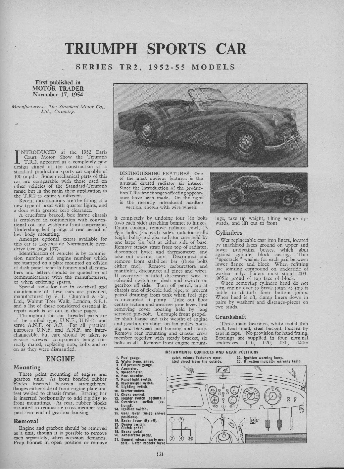
- Triumph TR2 17 November 1954,
- Triumph TR3 31 July 1957.
I will adding them to website in the future. In the meantime copies can be downloaded from here by clicking on the model you want.
Subscribe to:
Posts (Atom)